Structural Modeling
Instantiation of Basic Gates
- Primitives
gate는 primitives이다. 사용자가 만든 것이 아닌 주어진 것이며 사용자, simulation program이 모두 알고 있는 정보이다.
module basic_gates (x, y, z, f) ;
input x, y, z;
output f ;
wire a, b, c; // internal nets
// Structural modeling using basic gates.
nor g1 (b, x, y);
not g2 (a, x);
and g3 (c, a, z);
nor g4 (f, b, c);
endmodule
primitives는 module이름이 본인의 기능을 하는 것이나 마찬가지이다. 따라서 위와 같이 g1,g2,g3,g4라고 naming을 추가로 해주는 경우는 드물다. basic gate일 경우에는 instant의 이름을 선언해주는 건 선택적이다.
input / ouput port는 기본적으로 wire라고 생각한다. ( port구멍 뚫어서 꽂는 건 wire밖에 없으니)
Array of Instances
Gate들도 Array처럼 쓸 수 있다. ( gate 여러개를 set로 쓰는 느낌으로 )
Memory처럼 데이터를 저장하는 공간,,? 으로 보기에는 어렵다.
wire [3:0] out, in1, in2;
// basic array instantiations of nand gate.
nand n_gate[3:0] (out, in1, in2);
// this is equivalent to the following:
nand n_gate0 (out[0], in1[0], in2[0]);
nand n_gate1 (out[1], in1[1], in2[1]);
nand n_gate2 (out[2], in1[2], in2[2]);
nand n_gate3 (out[3], in1[3], in2[3]);
array로 쓰더라도 위와 같이 하나씩 따로따로 구현하는 것을 권장한다.
Port in Module (Port)
- 각 port는 기본적으로 wire 속성으로 선언 된다.
따라서 출력 port 단자의 값을 유지(저장)하려면 reg로 따로 선언해야한다.
(단, input, inout 형의 port는 reg로 선언할 수 없음)
- output port는 reg,net(Wire)모두 가능!
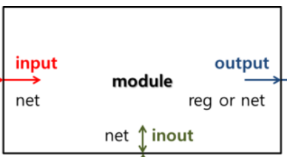
input port는 바깥에서 들어온 값 내가 갖다 쓰는 거니까 무조건 wire,
바깥으로 내보낼 때는 wire,reg(FF)모두 가능 (output은 둘 중에 하나 선택 가능)
input clk; // Clock input
input [15:0] data_in; // 16 bit data input bus
output [7:0] count; // 8 bit counter output
inout data_bi; // Bi-directional data bus
reg [7:0] count; // Output port can hold values
output port나갈 값을 저장해두었다가 나가게 하려면, 위와 같이 reg로 선언을 해주어야한다.
(// output을 어떻게 전해줄지 명시해주기 reg or net )
And / Or type ( N - input primitives)
and a1 (OUT, IN1, IN2); -- 2 input AND gate
and a2 (OUT, IN1, IN2, IN3); -- 3 input AND gate
Primitive module의 특징 중 하나는 입력의 개수에 제한이 없다는 것이다.
따라서 첫번째 port가 무조건 output이고 나머지는 input들이다.
Buffer ( N - output primitives )
buf b1 (OUT, IN); // simple buffer
not n1 (OUT, IN) ; // inverter
buf bf_2out (OUT1, OUT2, IN) ; // more than 2 outputs
buf와 not은 무조건 1개의 입력을 갖고 있으므로, 마지막 하나가 무조건 input이고 앞쪽 나머지는 output이다.
//아무튼! 앞쪽은 출력이고 뒤쪽은 input인 건 동일~!
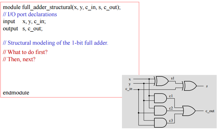
Example
1-Bit Full Adder
module이름 적고 -> input,output적고 ->,,,,,,
그림상, flip flop같은 output 필요 없음!! reg 필요없고 그냥 wire~!
4 -to-1 Multiplexer
module mux4_to_1_structural (i0, i1, i2, i3, s1, s0, out);
input i0, i1, i2, i3, s1, s0;
output out;
wire s1n, s0n; // Internal wire declarations
wire y0, y1, y2, y3;
// Gate instantiations
not (s1n, s1); // Create s1n and s0n signals.
not (s0n, s0);
and (y0, i0, s1n, s0n); // 3-input and gates instantiated
and (y1, i1, s1n, s0);
and (y2, i2, s1, s0n);
and (y3, i3, s1, s0);
or (out, y0, y1, y2, y3); // 4-input or gate instantiated
endmodule
main body 먼저 구현하고 상황에 따라 필요한 wire 추가하기~! wire먼저 선언하려 하지 않아도 됨!
그리고 gate의 instance 이름은 선택적이므로 쓰지 않아도 됨.
4-to-1 Multiplexer
// 4-to-1 Line Multiplexer: Structural Verilog Description
module multiplexer_4_to_1_st_v(S, I, Y);
input [1:0] S; //2bit input ( Vector type's wire )
input [3:0] I; //4bit input
output Y;

//0을 어디에 둘지 통일하기
wire [1:0] not_S;
wire [0:3] D, N;

not gn0 (not_S[0], S[0]);
not gn1 (not_S[1], S[1]);

and
g0(D[0], not_S[1], not_S[0]),
g1(D[1], not_S[1], S[0]),
g2(D[2], S[1], not_S[0]),
g3(D[3], S[1], S[0]),
g4(N[0], D[0], I[0]),
g5(N[1], D[1], I[1]),
g6(N[2], D[2], I[2]),
g7(N[3], D[3], I[3]);
or go(Y, N[0], N[1], N[2], N[3]);
endmodule
- vector type 표현
: 범위를 표현할 때 0의 위치를 통일한다.
- gate 여러개 한번에
: 위 예시 처럼 동일 gate에 대해서는 위에 gate를 한 번만 선언해주고 나머지는 instatnce이름을 지정하여
쉼표로 이어가며 여러개를 한 번에 표현할 수 있다.
2-to-4 Line Decoder with Enable
** Decoder(line활성화)와 Multiplexer(input뽑기)의 차이
: mux는 입력으로 받은 값들 중 하나를 그대로 출력으로 내보는 것이지만, decoder는 입력 신호에 따라 주어진 4개에 line(출력) 중 하나를 활성화시키는 역할을 한다. 입력이 그대로 나가는 것이 아니라 입력에 따라 활성화 되는 output값이 달라지는 것이다.
// 2-to-4 Line Decoder: Structural model
decoder_2_to_4_st_v (EN, A0, A1, D0, D1, D2, D3);
input EN, A0, A1;
output D0, D1, D2, D3;
wire A0_n, A1_n, N0, N1, N2, N3;
not go (A0_n, A0);
not g1 (A1_n, A1);
and
g3(N0, A0_n, A1_n),
g4(N1, A0, A1_n),
g5(N2, A0_n, A1),
g6(N3, A0, A1),
g7(D0, N0, EN),
g8(D1, N1, EN),
g9(D2, N2, EN),
g10(D3, N3, EN);
endmodule
위에서 표현된 wire N0, N1, N2, N3는 아래와 같이 vector 형식으로 표현할 수 있다.
//vector표현으로 (1) bit 선언 먼저 하고, (2) instance 이름 선언하기!
wire [3:0] N;
9-bits Parity Generator
module parity_gen_9b_structural(x, ep, op);

// I/O port declarations
input [8:0] x;
output ep, op;

wire c, d, e, f, g, h, j;

xor xor_11(c, x[0], x[1]); // first level
xor xor_12(d, x[2], x[3]);
xor xor_13(e, x[4], x[5]);
xor xor_14(f, x[6], x[7]);

xor xor_21(g, c, d); // second level
xor xor_22(h, e, f);

xor xor_31(i, g, h); // third level

xor xor_ep(ep, i, x[8]); // fourth level

xnor xnor_op(op, i, x[8]);

endmodule
- Parity bit
: 데이터 전송 중에 오류 검층을 위해 사용되는 bit
(( 데이터 전송 전에 ))
data에 0과 1이 몇개 있는지 검사하여, 특정 규칙에 따라 추가로 붙일 parity bit를 0으로 할지 1로 할지 결정한다.
even parity를 쓸 경우 data의 1의 개수가 짝수여야하고, odd parity를 쓸 경우 data의 1의 개수가 홀수여야 한다.
따라서 even parity 를 사용할 경우 데이터에 포함된 1의 개수가 이미 짝수일 때는 parity bit를 0으로 설정한다.
이러한 parity bit는 수신자가 데이터를 수신한 후, 이진 표현에서 1의 개수와 함께 전송된 parity bit를 비교하여
수신에 사용하였던 even pairty, odd parity에 따라 오류 여부를 판단한다.
'Quality control (2) > Digital System Design' 카테고리의 다른 글
| DSD - Dataflow Modeling(1) (0) | 2023.04.06 |
|---|---|
| DSD - Structural Modeling(3) / Unfamiliar data type / Hierarchical modeling / Gate delay / hazards (0) | 2023.04.05 |
| DSD - Structural Modeling(1) / gate primitives (0) | 2023.04.02 |
| DSD - Verilog Coding Basic (0) | 2023.04.02 |
| DSD - Verilog HDL-based design flow(2) / ASIC (0) | 2023.04.02 |