Structural Modeling
Modeling in Verilog
- Structurla Modeling
: a set of interconnected component
- dataflow modeling
: by interconnecting registers and a combinational logic put between them
- Behavioral Modeling
: concurrent algorithms
Structural Modeling
[GPT said]
Structural modeling refers to designing digital circuits using a structural descripton of the circuit.
The structural description of a circuit specifies how the components of the circuit are connected together to form a complete system.
//회로 구성요소들이 서로 어떻게 연결되어 있는가
In verilog, the components of a circuit are defined as modules.
Each module represents a functional unit in the circuit, such as an adder or a flip flop.
The modules are conneted together using wires and other signals to form the complete system.
//모듈로 구현
The Verilog language provides a set of predefined modules that can be used to build large circuits.
//큰 회로를 구현할만한 module들을 제공
These predefined modules include basic logic gates, such as AND, OR, and NOT gates, as well as more complex components, such as adders, multipliers, and memory blocks.
To create a circuit using structural modeling, the designer defines each module and its inputs and output. Then, the modules are instantiated(object화) and connected together using wires and signals.
//module( with input& output) 정의
- Structural style
: Model(ed) as a set of interconnected components
//module과 gate들과 switch들의 연결
- Components 종류
| Modules / UDPs (User Defined Primitives) | Modules/UDPs may or may not be synthesized. A gate-level moduel is usually synthesizable. (가장 많이 사용됨) |
| Gate primitives | There are 12 gate primitives (그냥 주는 단순한 것 / 수정 x ) Gate primitives are synthesizable. (종종 사용됨) |
| Switch primitives | There are 16 switch primitives. They are usually used to model a new logic gate circuit at switch level. They are not synthesizable, in general. (자주 사용되지 않음) |
Gate Primitives
- and / or gates
: multiple scalar inputs -> one scalar output
and / or gates는 basic한 logic operation들을 만들어 내기 위해 사용된다. (and.or를 조합하여 만듦)
( ex. and, or xor, nand, nor, xnor )
- buf / not gates
: one scalar input -> one or multiple scalar outputs
buf / not gates는 not operations을 수행하기 위해 사용되어지거나 and / or gate의 output을
일시적으로 저장하는 메모리 로서 사용된다(buffer). // controlled buffers
( ex. buf, not, bufif(), notif(), bufif1, notif1 )
** Verilog has built in primitives like gates, transmission gates, and switches. This are rarely used for in design work, but are used in post synthesis world for modeling the AISC/FPGA cells, this cells are then used for gate level simulation or what is called as SDF simulation.
//설계 업무에서 거의 사용되지 않으나, gate level simulation이나 SDF simultion에서 사용된다.
SDF ( Standard Delay Format ) : 전자 설계 분야에서 시뮬레이션 및 타이밍 분석을 위한 표준 데이터 형식
Logic Values and signal Strengths
| 0 | zero, low, false |
| 1 | one, high, true |
| z (or Z) | high impedance , floating |
| x (or X) | unknown, uninitialized //실제 board에서는 garbage 값이 생긴다. |
Use case of buf gates
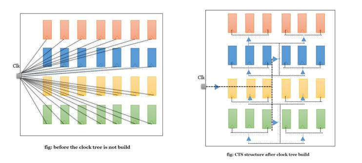
clock tree가 build되지 않은 상태에서는 clk delay가 생길 수 있어, synchronous(동기식)이 되기 어렵다.
clock의 미세 조정이 디지털 시스템 설계에서의 핵심이다. 여기서 clock의 미세조정이란, clock신호가 전체 디자인 내에서 동기화되고, 안정적으로 전달되는 것을 의미한다.
우측 clock tree가 build된 CTS구조는 주변 구조와 상관 없이 cllk의 신호만 보면 된다.
'Quality control (2) > Digital System Design' 카테고리의 다른 글
| DSD - Structural Modeling(3) / Unfamiliar data type / Hierarchical modeling / Gate delay / hazards (0) | 2023.04.05 |
|---|---|
| DSD - Structural Modeling(2) / instantiation / ports / basic example / parity bit (0) | 2023.04.05 |
| DSD - Verilog Coding Basic (0) | 2023.04.02 |
| DSD - Verilog HDL-based design flow(2) / ASIC (0) | 2023.04.02 |
| DSD - Verilog HDL-based design flow / FPGA (0) | 2023.04.02 |